PLIF systems are commonly used in the field of combustion to measure the concentration of individual combustion radicals in flames. Typical combustion radicals include OH, CH, NO, HCHO (CH2O), CN, NH, etc. Some of the radicals are excited by the energy of the flame itself to produce Chemiluminescence, which can be directly recorded by the intensified camera. Most radicals are ground-state in the flame, and after being excited by a laser of appropriate wavelength, they become excited radicals and release fluorescence in a specific spectral range to be detected.
In flames, light signals that can typically be detected include:
- Laser-induced fluorescence. Its light intensity is linearly related to the number of excited radicals, which is affected by various factors such as pressure.
- Flame background light (Chemiluminescence of different substances, visible light from high-temperature soot, etc.)
- Laser Mie scattering from particles in the flame, such as soot particles, incompletely burned oil droplets, etc.
- Rayleigh scattering of laser rays produced by molecules in the flame
- Incandescence produced by soot that absorbs laser energy
- Other non-target detection radical groups excited by the laser, such as PAHs, etc
- Other
Therefore, it is often easy to obtain image results with PLIF, but how to interpret measurement images requires professional background knowledge, thoughtful and meticulous measurement schemes, and certain experimental skills. Designed specifically for PLIF applications, we explore how the RapidIntense family of image intensifiers can help users achieve accurate measurement results from multiple dimensions.
For example, a 10Hz PLIF system only considers the use of P43 anode, while a kHz PLIF system only considers the use of a P46 anode. So here will not talk about the difference between P43 and P46. In the same way, the differences between different cathode materials will not be introduced at length. If readers are interested, welcome to contact us.
Gate width
The time scale of Mie scattering and Rayleigh scattering is about equal to the pulse width of the laser pulse, which is in the order of 5-10ns; The fluorescence lifetime induced by pulsed laser is in the order of 10-20ns; The incandescence lifetime of the soot excited by the laser is in the order of 80ns-1us; The flame background light is persistent.
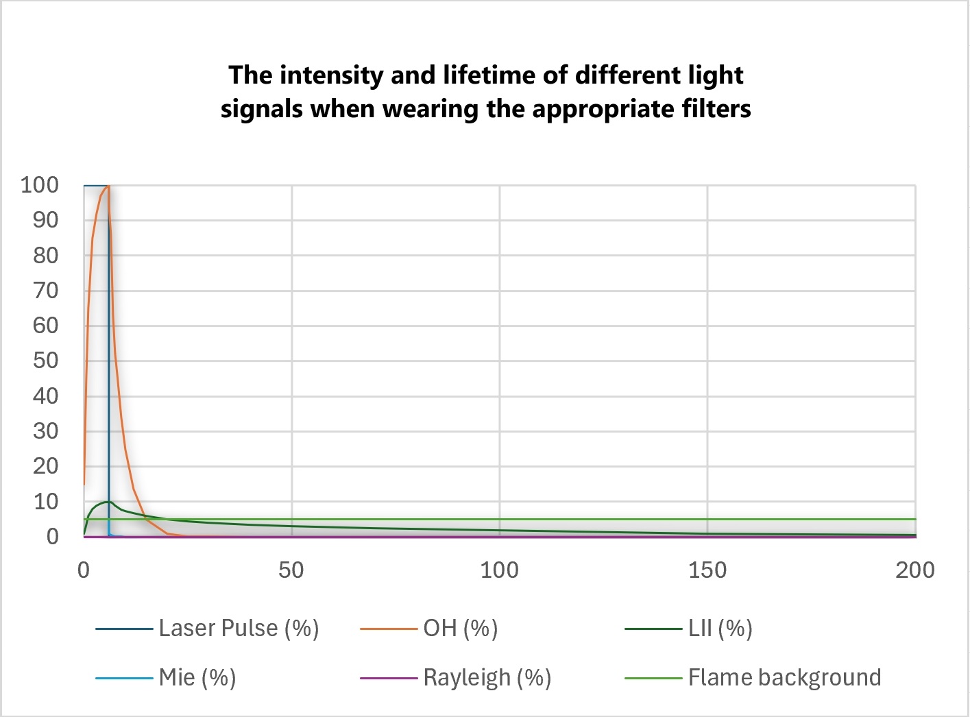
Therefore, when the integration time is small enough, i.e., the gate width of the image intensifier is small enough, and the ratio of the light intensity of the fluorescence signal (signal) to the ingested light intensity of all other light (noise) is high enough, we can obtain an ideal PLIF result. Conversely, when the gate width is wider, the higher the noise ingested by the intensifier and the weaker the signal-to-noise ratio of the effective signal obtained.
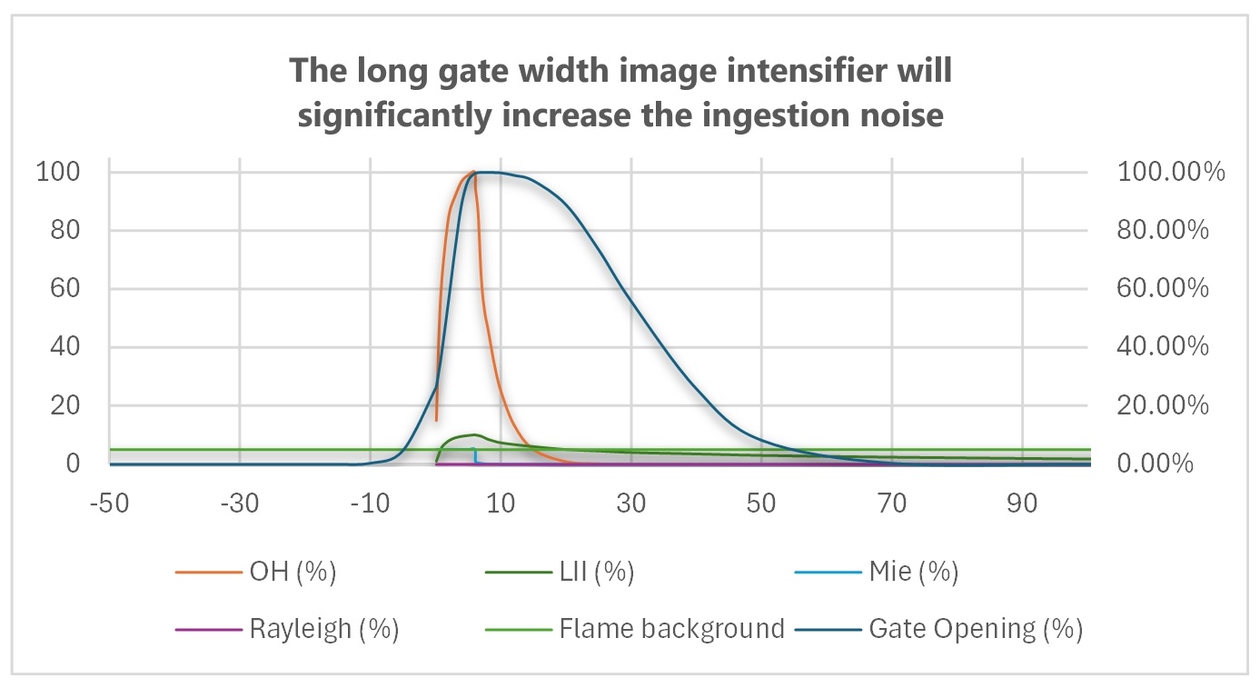
In addition, it is important to note that even with the appropriate filters, some Mie scattering and LII signal will still enter the gate width detection range. This part of the noise is amplified as the gate width of the image intensifier increases. Generally speaking, Mie in flames is mainly produced by soot and incompletely burned oil droplets; The LII entering the detection wavelength range is mainly small-particle soot. Therefore, in the actual engineering measurement of fuel-rich flames, the long door width image intensifier is almost unusable.
The door width of an image intensifier is related to its cathode manufacturing process. Generally speaking, when the door width of the purchased product is 40ns and above, the cathode of the image intensifier does not have the ability to open and close quickly, and its opening and closing process is slow, and it shows a slow opening process from the center of the image to the edge. As you can see from the figure below, a long door width image intensifier will capture higher noise than a short door width image intensifier even at the same door width.
Clear aperture
The clear aperture of the image intensifier is an important indicator, and its ability to acquire light is squared to the ratio of the diameter. When shooting the same field of view, the 25mm image intensifier captures twice the light intensity of the 18mm product. In addition, due to the mature processing technology of the photocathode, compared with the image intensifier with a larger aperture, the 25mm model has a more uniform opening time and phase delay in the entire photocathode plane. The 25mm phosphorescent screen also has better image brightness uniformity.
The 25mm clear aperture also gives us more flexibility in our imaging camera options. Not only can we adapt to small-sized sensors such as PIV cameras by shrinking the field of view, but we can also adapt them to scientific-grade large-size sCMOS with ultra-high sensitivity.
Output resolution
The 25mm aperture image intensifier is not perfect everywhere, and its output resolution is inferior to that of the 18mm counterpart. An image intensifier with an 18mm aperture typically outputs a resolution of 41-62lp/mm, while a 25mm product has a resolution of 21-35lp/mm. But does that mean you can’t get a sharp image with a 25mm product? Not really.
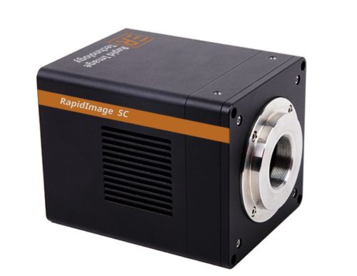
Taking the RapidImage SC high-sensitivity camera as an example, its pixel size is 12um, the imaging resolution is 2.3MP, and for easy calculation, when coupled to the image intensifier at 1:1, the imaging resolution of the camera is 41.7lp/mm. Just enough to meet the Nyquist criterion, it can clearly image the image intensifier with an output resolution of 21lp/mm. Therefore, when using this camera, an output resolution of more than 21lp/mm does not result in sharper images.
On the one hand, when coupling to a small pixel camera, we increase the pixel size by binning, because image resolutions of more than 2-4 megapixels are of little significance to PLIF (in contrast, the vector resolution of PIV is often only about 200 x 200); On the other hand, we can improve the imaging resolution on the camera side by adapting the appropriate relay lens.
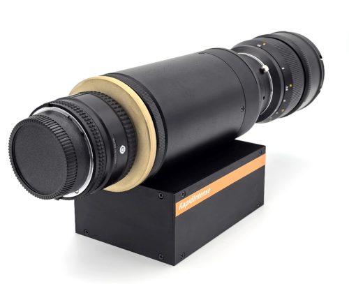
Relay lens
There are three main factors to consider in the selection of relay mirrors. 1. Relay ratio; 2. Aperture; 3. Resolution. In our database, we have collected a variety of relay mirrors with different relay ratios to meet the adaptation needs of different camera sensors.
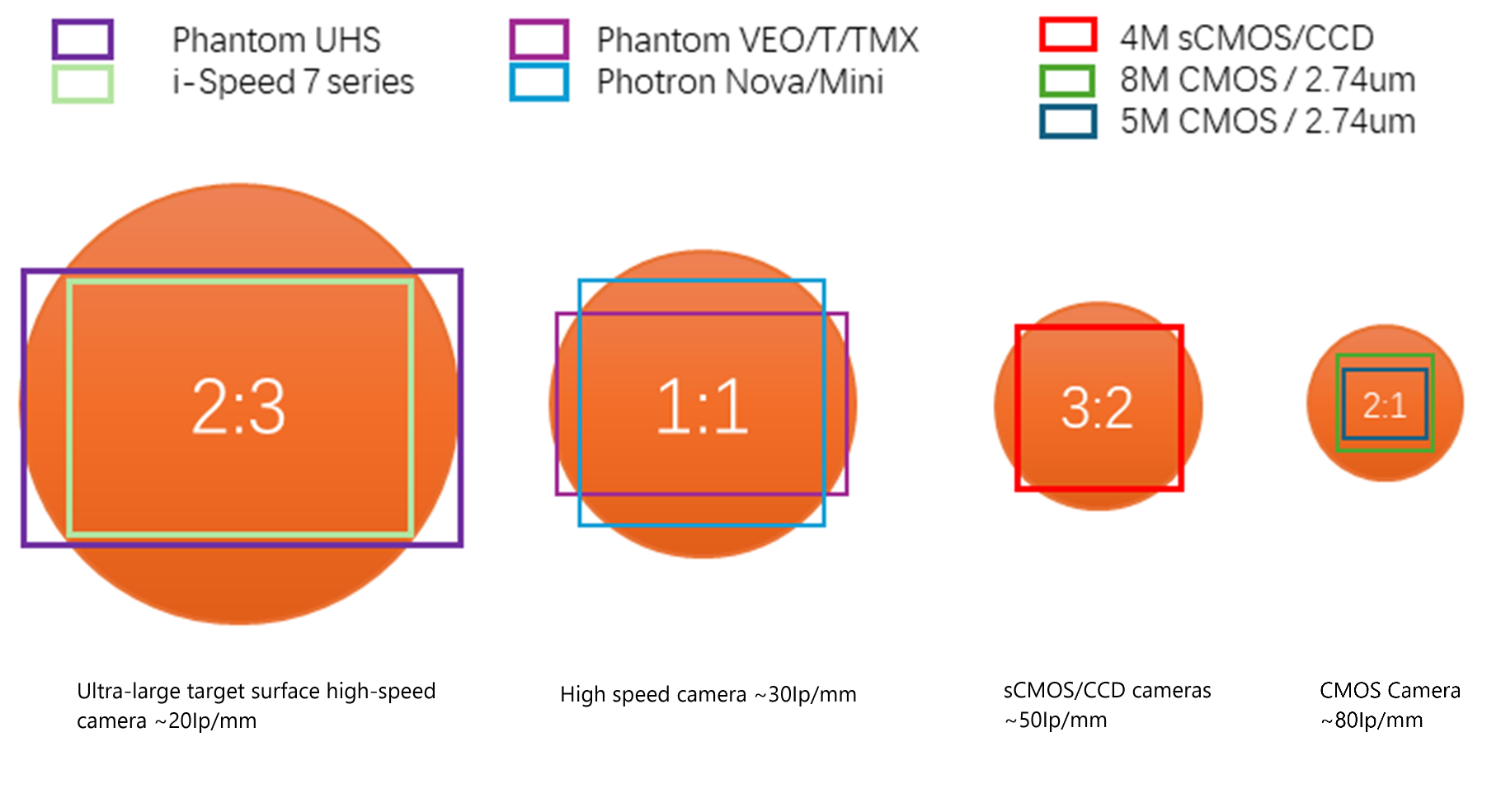
Field of view coverage and highest output resolution of different target cameras
Photocathode quantum efficiency
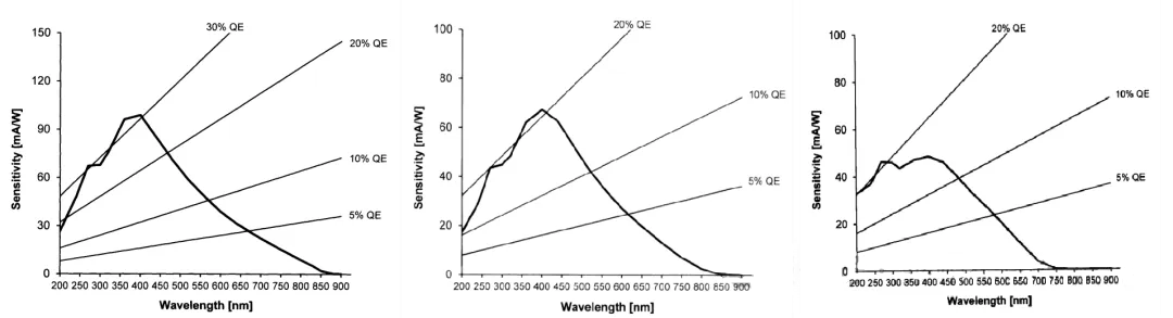
The quantum efficiency of a photocathode is affected by a number of factors. On the one hand, there is the cathode material, such as S20, S25, etc. In ultraviolet measurement, S20 is a commonly used material, depending on the specific formulation, derived from various names, such as S20+, S20B, S20 super, High QE Blue, etc., in essence, by changing the base formula and process of S20, slightly improve the quantum efficiency in the ultraviolet band. However, this quantum efficiency will vary from batch to batch; Products with a 100ns gate width/55ns gate width/3-5ns gate width will also lead to significant differences in quantum efficiency due to different cathode surface processes. Taking the factory test report of several 18mm products of an imported brand as an example, we can see this difference.
Gain
The gain of an image intensifier is often given by the manufacturer test of the image intensifier module. However, due to the fact that there is no unified standard for this gain test, it is often impossible to compare products between different manufacturers, not only numerical values, but also different manufacturers and even the marked gain units are different.
In addition, the maximum gain of the image intensifier is often of little significance in PLIF testing, because when the gain is turned on at 60-80%, the image noise increases significantly, which can greatly affect the quantitative measurement of PLIF. Equally important is the dynamic range for PLIF applications.
Output uniformity
There is a certain non-uniformity in the output of the phosphorescent screen. For most PLIF measurements, the user does not calibrate the non-uniformity of the entire optical system. However, when the uniformity of the phosphorescent screen output is too poor, greater uncertainty will be introduced into the measurement. The following is a comparison of the uniformity of the RapidIntense prototype phosphorescent screen and an imported model of 25mm phosphorescent screen.
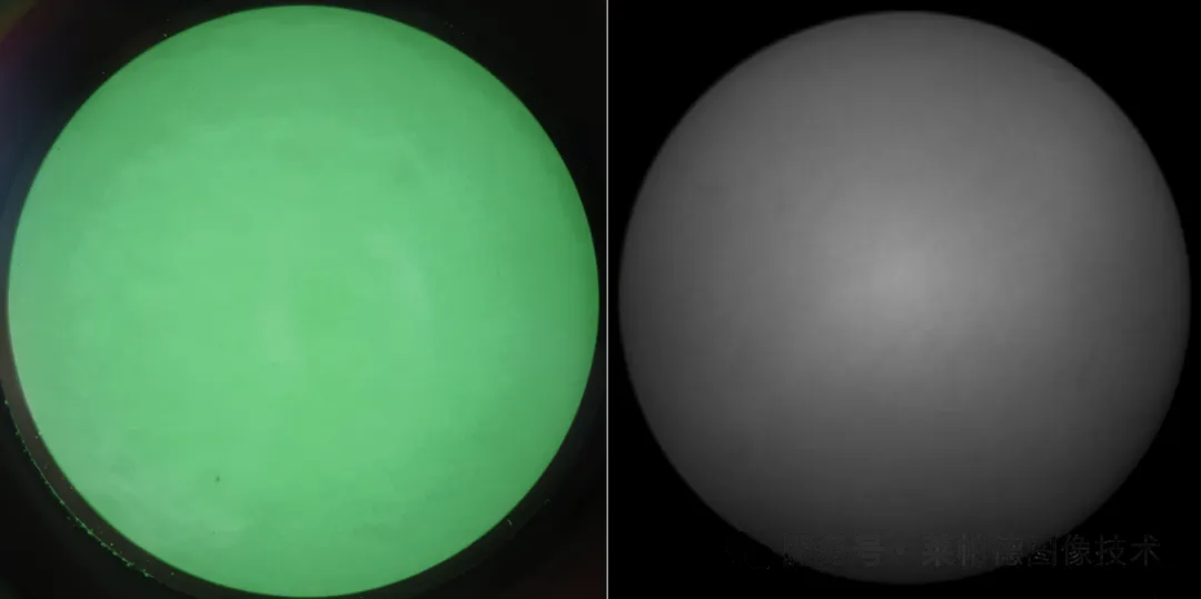
Uniformity of RapidIntense H/2 phosphorescent screen (left) and 25mm phosphorescent screen of an imported model (right)
To sum up, although the image intensifier is a stereotyped product, in terms of product design, we have optimized and selected many aspects according to the actual test needs of PLIF. In the final actual performance, we also lived up to expectations, and in the comparative test with an imported 18mm model product, we ensured that the test conditions were completely consistent, and the obtained PLIF signal light intensity reached nearly 3 times that of the imported product. Ensuring consistent test conditions include:
- The laser energy remains the same, and the overall optical path remains the same
- Same stable flame and filter
- The lens model and aperture are the same
- The image intensifier gain is consistent
- The relay ratio and number of apertures of the relay mirror are the same
- The camera model and all exposure and time-lapse parameters are the same
- Same number of samples and arithmetic mean
- The contrast settings of the images are consistent
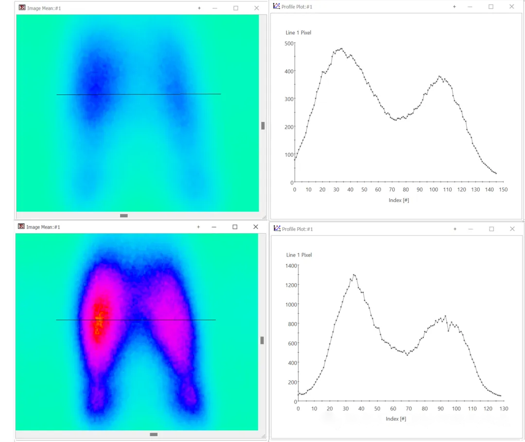
OH PLIF measurement result image and grayscale profile plot. An imported 18mm model (above); RapidIntense H/2 (lower)
The article is full of dry information, and it may be slightly difficult to understand. Welcome to like + collect and digest it slowly, or forward it to other colleagues to discuss together~ If you have any questions, please leave a message, or feel free to contact us!